Inputs and Outputs
The following features related to IO will be included in the system.
Analog and Thermocouple Input Alarms
Each analog and thermocouple input will have a configurable working range assigned to it. If a reading from an input is outside of this range, the following will take place depending on the nature of the input:
-
If the out of range input is used for monitoring only, an alarm will be raised
-
If the out of range input is used for control, an alarm will be raised and the process will be put on hold
Analog and Thermocouple Input Calibration
All thermocouple and analog inputs are processed through a two-point calibration algorithm. The algorithm uses the following formula:
-
Process value = ((Output2 – Output1) / (Input2 – Input1) * (Value – Input1)) + Output1 where:
-
Input1 – first measured value at the time of calibration
-
Output1 – what Input1 should have been
-
Input2 – second measured value at the time of calibration
-
Output2 – what Input2 should have been
-
Value – currently measured value
-
Process Value – used for process control and monitoring
-
Block Valve Diagnostics
-
A block valve may be equipped with position sensing switches. If so equipped, the PLC will check valve position switches against the commands sent to the solenoid. The following failures will be detected:
-
Switch flunk – both switches are made at the same time – one switch failed closed.
-
Stuck valve – Valve did not reach the desired open or closed state
-
Failed feedback switch – One switch failed open or valve is stuck in mid position
-
Proportional Valve Diagnostics
A flow control valve may be equipped with 4-20 mA position feedback. If so equipped, the system will detect discrepancy and will raise a valve fail alarm. This status will also be indicated on SCADA chamber display. The flow control valve discrepancy will be determined as follows:
-
If the commanded opening differs from actual opening by more than 10 % of the full scale timer starts
-
Each time the commanded and measure openings are within 10% the timer accumulated value is reset and the timer will stop timing
-
When the accumulates more than 30 seconds, a failed flag is set and an alarm is raised
-
When the commanded and measure openings are within 10%, the failed flag is reset and the alarm is cleared
Thermocouple and Analog Input Calibration
If your version of AccuSOLO is NOT licensed for Calibration Module, calibrations must be performed via the sensor status pop-up. All thermocouple and analog inputs are processed through a two-point calibration algorithm. The algorithm uses the following formula:
-
Process value = ((Output2 – Output1) / (Input2 – Input1) * (Value – Input1)) + Output1 where:
-
Input1 – first measured value at the time of calibration
-
Output1 – what Input1 should have been
-
Input2 – second measured value at the time of calibration
-
Output2 – what Input2 should have been
-
Value – currently measured value
-
Process Value – used for process control and monitoring
-
The Sensor Calibration (Inputs and Outputs ) popup window displays the following information:
-
Device tag and description
-
Input reading values 1 and 2
-
Output standard values 1 and 2
Note:
-
Calibration of chamber sensors is only enabled when the chamber enters the “Dormant” sequence and Stopped mode.
-
Closing the sensor status pop-up will clear all entered values. To avoid this, open a new session of the AccuSOLO client that is dedicated solely to performing calibration.
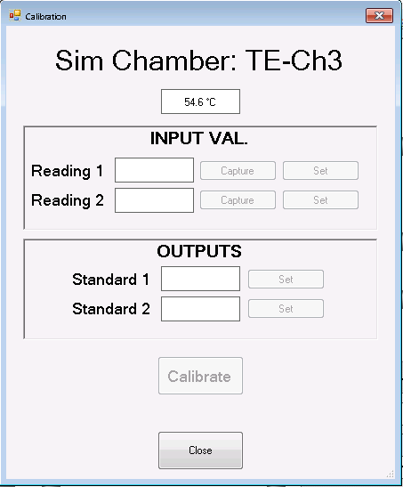
The following commands are available:
-
Capture – Selecting this button will cause the control system to display the sensor’s current reading
-
Set – Selecting this button will bring up the Change Set-point form, allowing the operator to enter and save a new value
-
Calibrate – Selecting this command will calibrate the sensor
Tip: The sensor can be calibrated only if Input Reading 1 does not equal Input Reading 2, and Output 1 does not equal Output 2.
I/O Failure Detection
The system will have the capability of detecting a situation where a PLC (chamber and/or common) is reading stagnant values from an I/O module:
-
Alarm 472: when the PLC detects that an analog sensor measurement has been stagnant for longer than a factory present delay, an alarm will be raised.
-
The alarm text will identify the sensor (device ID) and Module and Channel that are affected.
-
Disabling the sensor will clear the alarm.
-
The timer for the delay will clear only after the sensor readings have changed.
-
-
If a module becomes disconnected, a device has lost connection alarm 473 will be raised for all configured I/O on that module without any delay.
-
The alarm text will identify the sensor (device ID) and Module and Channel that are affected.
-
The alarm will clear once the module has re-connected to the PLC.
-